Choose nichrome wire size by calculating the required resistance from voltage and power, then checking which diameter and length fit the heating element. Confirm the alloy, operating temperature, surface load, and support before finalizing the wire.
A spool label can tell you the diameter. It cannot tell you whether the finished heater will fit its housing or remain within its temperature limits. This guide connects those decisions with a size chart, a worked calculation, and the specifications needed for a useful quotation.
Key Takeaways
- Smaller round wire has more resistance per metre when alloy and temperature remain the same.
- AWG is a diameter designation; higher gauge numbers indicate thinner wire.
- The required nichrome wire size depends on both electrical targets and element geometry.
- Cold resistance and resistance during operation can differ, so use the correct temperature factor.
- A calculated length is a starting point for design review, not proof of the operating temperature.
Start With the Inputs That Determine Nichrome Wire Size
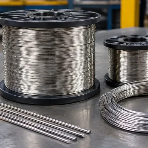
Start with the supply voltage, target heating power, alloy grade, and available space. Record whether the power target applies to one element or several connected elements. A series or parallel arrangement changes the resistance each element needs.
Next, distinguish the process temperature from the wire temperature. The furnace setpoint does not directly specify the temperature of the element. Heat transfer, support, atmosphere, and surface load all affect that relationship.
For an initial nichrome wire size calculation, collect:
| Input | What to Record |
|---|---|
| Electrical supply | Voltage across the element and AC/DC arrangement |
| Power target | Rated power per element and control method |
| Material | Exact alloy grade and resistivity at a stated temperature |
| Thermal conditions | Intended wire temperature, atmosphere, and duty cycle |
| Mechanical envelope | Available length, coil diameter, support, and terminals |
| Acceptance criteria | Diameter tolerance, cold resistance, and test temperature |
Illustrative Scenario: A Purchase Request With No Resistance Target
An equipment buyer asks for 0.5 mm wire because the previous spool carried that diameter. The engineering drawing, however, specifies a finished element resistance and a fixed installation length. Matching the old diameter alone leaves the new order incomplete.
The useful next step is to recover the alloy grade, cold resistance, and element drawing. This teaching scenario shows why a nichrome wire size request should include electrical and mechanical requirements together. It is not a customer case or a reported production outcome.
If those requirements are incomplete, send SPARK the available drawing and heating conditions before choosing a final diameter. Specify which values are known and which still require review.
Nichrome Wire Size Chart: AWG, Diameter, and Resistance
American Wire Gauge (AWG) specifies nominal round-wire diameter. A smaller gauge number means a larger diameter. Metric diameter should accompany AWG on an industrial order so the specification remains clear.
For reference, Remington Industries’ current Nichrome 80 data sheet lists gauge, diameter, and resistance at 20°C. Its values describe its own material. Do not treat another supplier’s resistance table as the acceptance specification for a Gitane order.
Calculated Resistance for a Stated Alloy
The chart below uses conventional nominal AWG diameters and a resistivity of 1.09 Ω·mm²/m at 20°C. That resistivity is published on the SPARK Cr20Ni80 product page. Resistance values are calculations using unrounded nominal diameters, not batch measurements or guaranteed tolerances.
| AWG | Nominal Diameter, mm | Calculated Resistance at 20°C, Ω/m |
|---|---|---|
| 18 | 1.024 | 1.324 |
| 20 | 0.812 | 2.106 |
| 22 | 0.644 | 3.348 |
| 24 | 0.511 | 5.324 |
| 26 | 0.405 | 8.466 |
| 28 | 0.321 | 13.461 |
| 30 | 0.255 | 21.404 |
| 32 | 0.202 | 34.033 |
Use this nichrome wire size chart to compare candidate diameters. Confirm the supplied diameter, grade, and resistance limits before placing an order. Rounding a diameter and then recalculating resistance can produce a slightly different table value.
A metric diameter is not always an exact AWG equivalent. For example, 0.5 mm is close to 24 AWG, but the nominal 24 AWG diameter is about 0.511 mm. Keep the requested metric size when the drawing specifies it.
How Diameter Changes the Required Length
For round wire, cross-sectional area is A = πd²/4. Resistance per metre is ρ/A, where ρ is resistivity and d is diameter. Use consistent units: diameter in mm, area in mm², and length in metres with the resistivity above.
At fixed alloy, temperature, and length, doubling diameter increases area fourfold and reduces resistance to one-quarter. If the required total resistance stays fixed instead, the thicker wire needs four times the length. These relationships explain why nichrome wire size cannot be selected separately from the available element space.
How to Choose Nichrome Wire Size for Voltage and Power
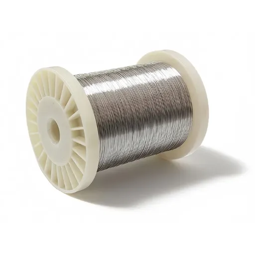
Calculate the target resistance first. Then compare candidate diameters against length, heat transfer, and the mechanical envelope. Changing nichrome wire size without recalculating the rest of the element can change both power and fit.
Step 1: Calculate the Operating Resistance
For a resistive element at its intended operating condition:
Rhot = V²/P
Here, V is voltage across the element, P is electrical power, and Rhot is resistance at the operating temperature. For AC, use RMS voltage under the applicable supply conditions. A controller or multi-element circuit may require a separate electrical analysis.
At fixed voltage, lower resistance means higher power. A replacement element with the right dimensions but the wrong resistance can therefore change the heater’s electrical load.
Step 2: Convert Hot Resistance to Cold Resistance
Use the selected grade’s temperature factor, Ct:
Rhot = Ct × R20, so R20 = Rhot/Ct.
R20 is resistance at 20°C. SPARK’s Cr20Ni80 page publishes Ct = 1.04 at 800°C. Use a different factor if the grade or intended wire temperature changes; confirm the applicable value with the supplier.
The Kanthal Nikrothal 80 data sheet also provides a temperature-factor table for its own alloy. It is a useful example of the data format, not proof that branded alloys are interchangeable.
Step 3: Calculate Length for Each Candidate Diameter
Calculate resistance per metre at 20°C, then divide the target cold resistance by that value:
L = R20/(ρ/A)
Compare at least two practical diameters when the installation allows it. A thinner candidate needs less length for the same resistance, while a thicker candidate needs more. The preferred nichrome wire size must also suit forming, support, terminals, and heat distribution.
Do not mix cold resistivity with a hot resistance target without applying the temperature factor. State the reference temperature beside every resistance value in the calculation and purchase specification.
Step 4: Check Surface Load and Physical Fit
For a round active wire length, approximate lateral surface area is πdL. Divide element power by the relevant surface area to estimate surface load. Convert units before reporting W/cm².
Surface load alone does not establish an allowable operating temperature. Check the alloy guidance, atmosphere, heat transfer, duty cycle, support, and element arrangement. Closely spaced coils or shielded sections may behave differently from an exposed straight wire.
For coil diameter, pitch, and support questions, use SPARK’s furnace heating coil selection guide. A nichrome wire size calculation and a coil drawing should be reviewed together.
Worked Example: Calculate Diameter, Resistance, and Length
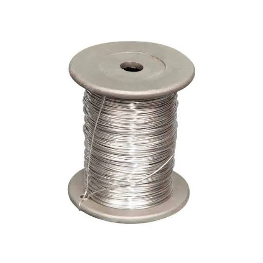
Illustrative Scenario: Comparing a 0.5 mm Candidate
Assume a teaching example with a 24 V supply, 24 W target power, Cr20Ni80 wire, and an intended 800°C wire temperature. Use the published 20°C resistivity of 1.09 Ω·mm²/m and Ct of 1.04. These assumptions demonstrate the method; they do not establish that this heater will reach 800°C.
The target hot resistance is 24²/24 = 24 Ω. Dividing by 1.04 gives a cold resistance target of about 23.077 Ω. For a metric 0.5 mm diameter, area is π × 0.5²/4 = 0.19635 mm².
Resistance per metre at 20°C is 1.09/0.19635 = 5.551 Ω/m. Required active wire length is therefore 23.077/5.551 = 4.157 m. Retain unrounded values during calculation and round only the reported results.
| Check | Calculated Result |
|---|---|
| Hot resistance target | 24 Ω |
| Cold resistance target at 20°C | 23.077 Ω |
| Wire diameter | 0.500 mm |
| Cold resistance per metre | 5.551 Ω/m |
| Active length | 4.157 m |
| Approximate lateral surface area | 65.3 cm² |
| Nominal surface load at 24 W | 0.368 W/cm² |
This nichrome wire size candidate meets the arithmetic resistance target. The next task is to check whether the length can be formed and supported in the required space. The surface-load result is a comparison value, not an approved rating.
What Changes With a Larger Diameter?
A 1.0 mm candidate has four times the cross-sectional area of 0.5 mm wire. Under the same assumptions, it needs about 16.628 m to meet the cold resistance target. Its active lateral surface area is eight times larger, so nominal surface load is one-eighth as high.
That comparison does not automatically make thicker wire preferable. It may require a different coil arrangement, more support, or a larger installation envelope. Choose nichrome wire size by testing the complete design against the constraints, rather than choosing the largest available diameter.
Before ordering, compare SPARK’s NiCr alloy options and request confirmation of the grade data and resistance tolerance used in your calculation.
Match the Wire to the Heating Element and Purchase Specification
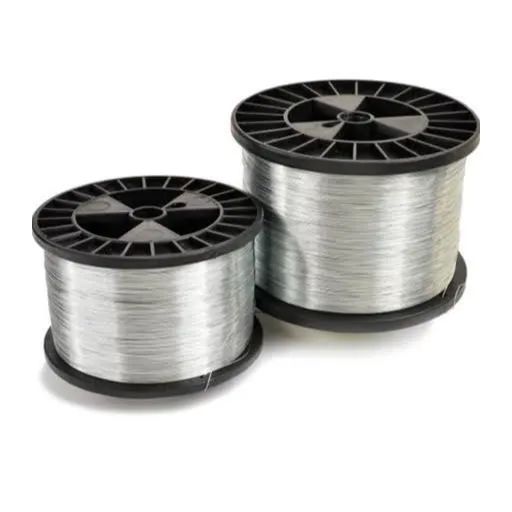
Electrical resistance is only one part of the finished element. The selected nichrome wire size must fit the support system, connections, heating pattern, and installation. Keep those requirements visible on the drawing.
Thin Wire, Thick Wire, and Ribbon
Thin nichrome wire provides higher resistance per metre. It can achieve a target resistance with a shorter conductive path, but diameter alone does not establish its suitability for a compact heater. Check handling, forming, terminals, and surface load.
Thick nichrome wire provides lower resistance per metre. It needs a longer path for the same resistance and must fit the available space. Review its forming and support requirements instead of assuming that extra thickness guarantees longer service life.
For ribbon, specify width and thickness rather than AWG. Cross-sectional area is width × thickness. A ribbon with the same cross-sectional area and alloy as round wire has the same calculated resistance per metre, but a different exposed perimeter and mounting geometry.
| Form | Required Dimensions | Main Geometry Check |
|---|---|---|
| Round wire | Diameter or AWG plus metric diameter | Coil diameter, pitch, and support |
| Ribbon | Width × thickness | Bend orientation, clearance, and support |
| Finished element | Wire dimensions plus assembly drawing | Active length, terminals, and installed envelope |
Keep the nichrome wire size designation distinct from the finished coil diameter. For example, 0.5 mm wire wound into a coil remains 0.5 mm wire. The coil’s outer diameter is a separate drawing dimension.
Check the Coil, Connections, and Measurement Conditions
An element drawing should distinguish the active heating length from tails and connections. Their resistance and thermal conditions can affect the finished assembly. Specify where resistance is measured and whether the acceptance value includes the terminals.
For a tightly toleranced low-resistance element, account for test leads and contact resistance in the measurement method. The measured cold resistance should be compared at the specified temperature. Testing a warm coil against a 20°C target can create a misleading rejection.
SPARK’s electric heating elements provide the relevant product path when the requirement concerns a finished assembly. For broader grade selection, consult the nickel-chromium alloy wire guide.
Illustrative Scenario: A Replacement That Fits but Draws Different Power
A maintenance team finds replacement wire that fits the existing ceramic support. The new material has a different resistance per metre, even though its diameter looks similar. Installing the same length would not reproduce the original element resistance.
The team should compare grade, cold resistance, active length, and connection details before accepting the replacement. This illustrative scenario explains why physical fit cannot validate nichrome wire size by itself. It makes no claim about a real customer or measured savings.
Prepare a Complete Request for Quotation
When a project considers another grade, review its specific product data, such as SPARK Cr30Ni70. Confirm the selected nichrome wire size again using that grade’s electrical data.
A useful RFQ turns the chosen nichrome wire size into a measurable requirement. Include the nominal dimension, tolerance, and reference temperature. If the drawing specifies finished resistance, state its permitted range too.
- Exact alloy grade and required material documentation.
- Diameter in mm, with AWG if relevant, or ribbon width and thickness.
- Cold resistance target, tolerance, and measurement temperature.
- Active wire length or finished element drawing.
- Supply voltage, target power, and connection arrangement.
- Intended wire temperature, atmosphere, and heating cycle.
- Coil dimensions, support, terminals, and installation space.
- Quantity, packaging needs, and required inspection records.
Keep requested values separate from confirmed supply terms. A public product range is not confirmation of stock, a particular tolerance, or a delivery date. The GITANE company profile identifies the manufacturer; the quotation should confirm the specification for your order.
Frequently Asked Questions
Is There One Best Nichrome Wire Size for Heating?
No. The appropriate diameter depends on voltage, power, alloy, temperature, length, and element geometry. Start with the resistance target, then compare practical diameters against the installation and operating conditions.
Is 0.5 mm Nichrome Wire the Same as 24 AWG?
They are close but not identical nominal dimensions. Standard 24 AWG is about 0.511 mm. Specify the metric diameter on the drawing when that value controls the required nichrome wire size.
Can I Calculate Temperature From Voltage and Wire Diameter?
Not from those inputs alone. Electrical power also depends on resistance, and equilibrium temperature depends on heat loss and the surroundings. Use the actual element arrangement and thermal conditions when evaluating temperature.
Where Can I Find Additional Resistance Charts?
WireTronic’s resistance-wire charts include gauge and temperature-related references. Check the alloy, units, and test conditions before applying any chart. Use the selected supplier’s data for order acceptance.
Can I Substitute Another NiCr Grade Without Changing the Drawing?
Only after checking its resistivity, temperature factor, operating limits, and forming requirements. The same nichrome wire size does not establish grade equivalence. Review the original cold resistance and finished geometry before approving a substitute.
Confirm the Specification Before Ordering
A sound nichrome wire size decision connects the resistance target to a practical diameter, length, and supported element. Record the grade and reference temperature, apply the correct hot-to-cold factor, and check the complete assembly before treating the calculation as a final specification.
Keep the nichrome wire size calculation sheet with the drawing so purchasing and inspection use the same assumptions. For a SPARK quotation, send your wire dimensions, resistance target, and operating conditions. Include the element drawing when the requirement extends beyond straight wire.