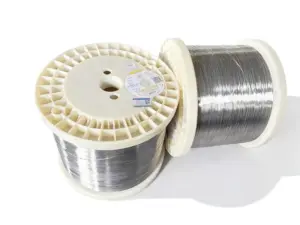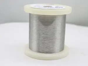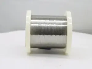
A furnace heating coil is a resistance heating element that converts electrical energy into heat. Select it against the material, electrical target, dimensions, atmosphere, and support arrangement required by the furnace.
For industrial buyers, choosing a suitable coil involves more than checking the furnace temperature. Its dimensions, electrical requirements, installation space, and support method must also be considered. This guide keeps those inputs together and shows how to turn them into a drawing, a material review, and a usable purchase specification.
Key Takeaways
- Define wire diameter, coil diameter, pitch, heated length, and cold ends separately.
- A nichrome heating coil is a NiCr option, not a description of every furnace element.
- Use resistance at the stated temperature when checking voltage and power.
- Match the supports, atmosphere, and heating cycle to the actual element design.
- Agree on dimensions, resistance limits, test methods, and supply condition before ordering.
What a Furnace Heating Coil Must Specify
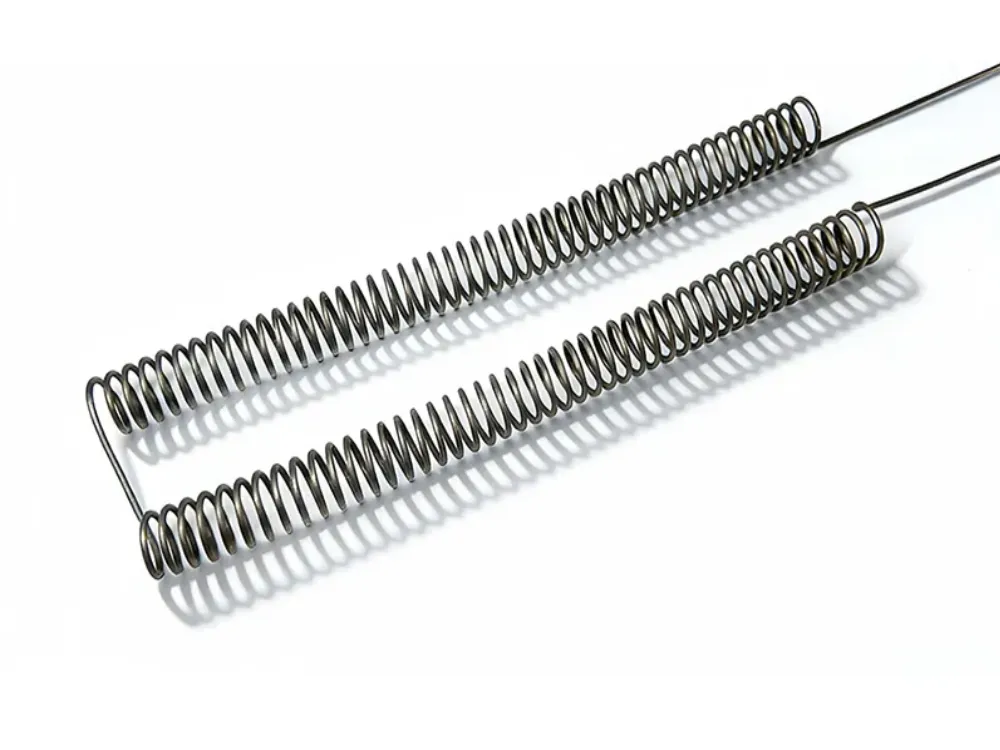
A heating coil for furnace applications is usually made from resistance wire or ribbon. The material is wound or formed so that the required heated length fits inside the available space. Different heating zones may need different layouts.
Describe the Complete Element
A furnace heating coil specification must identify more than the wound wire. Include its supports, terminal positions, connections, and the space available for thermal movement. Otherwise, a replacement may fit one dimension while conflicting with another part of the assembly.
In muffle furnaces, coils may be placed in wall grooves or mounted on ceramic supports. Other arrangements suspend the element between insulated points. These layouts create different mechanical and heat-transfer conditions.
Indeeco’s overview of electric heating elements describes industrial element forms, support arrangements, and operating factors. Its examples help frame the review; they do not establish dimensions for a specific SPARK element.
Keep Open Coils and Other Heater Forms Distinct
An open coil exposes the resistance material to its surroundings. A metal-sheathed heater encloses the resistance material within an insulated assembly. Their design and acceptance requirements should not be mixed.
This guide addresses industrial resistance elements, not induction coils or domestic HVAC repair procedures. Name the furnace type and heating-zone arrangement when requesting a furnace heating coil. A photograph can help explain the layout, but it does not replace missing electrical or material data.
For an initial review, send GITANE the furnace conditions and existing element drawing. Mark unknown inputs clearly so that the material discussion can address them.
Select NiCr or FeCrAl for the Operating Conditions
NiCr and FeCrAl are common resistance-alloy families. The suitable grade depends on the operating conditions and heating element design. A furnace heating coil should therefore be specified by its named material rather than a general family label alone.
Nichrome Heating Coil Materials
Nichrome refers to nickel-chromium resistance alloys, including grades with iron in their composition. A nichrome heating coil may be useful in an application that needs a particular combination of electrical and mechanical properties. The actual grade still needs review.
SPARK’s NiCr alloy range provides a starting point for material questions. Confirm the selected product’s current data, temperature conditions, and supply form. Do not apply one NiCr grade’s resistance factor to another.
FeCrAl Heating Coils and Formed Elements
FeCrAl alloys are often used in high-temperature electric heating applications. Under suitable oxidizing conditions, an alumina layer forms on the surface during operation. The atmosphere and contaminants affect how the material performs.
Gitane lists grades such as 0Cr25Al5, 00Cr20Al6, and 0Cr23Al5 in its FeCrAl material range. These are candidates to assess against the application, not interchangeable choices for every furnace heating coil.
For the wider material decision, use the NiCr and FeCrAl furnace wire selection guide. Keep this page focused on coil geometry, electrical checks, support, and the order specification.
Compare Conditions Before Comparing Ratings
The furnace setpoint does not always equal the actual coil temperature. Depending on heat transfer, surface loading, and element layout, the wire may operate at a higher temperature. Select the grade against the actual element requirement.
The nichrome wire temperature guide explains the difference between continuous ratings, melting points, and measured temperatures. A furnace heating coil review should record which temperature each number describes.
Define Furnace Heating Coil Dimensions Clearly
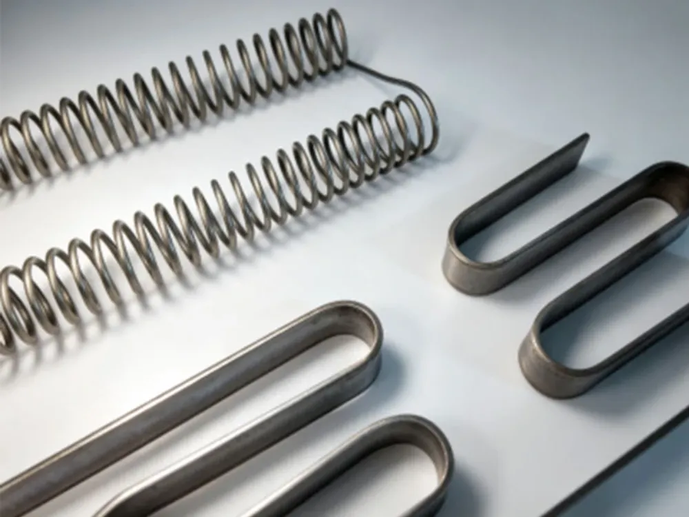
Wire size and coil size describe different things. Likewise, the length occupied by a coil is not the length of wire used to make it. Define these terms on the drawing before comparing quotations or calculating resistance.
Name Each Diameter and Length
| Drawing term | What to specify |
|---|---|
| Wire diameter, d | The diameter of the round resistance wire |
| Coil outside diameter, OD | The outside envelope of the wound coil |
| Coil inside diameter, ID | The clear opening inside the coil |
| Mean coil diameter, Dm | Diameter measured through the wire centerline |
| Axial pitch, p | Advance along the coil axis over one complete turn |
| Turn clearance | The gap between adjacent wire surfaces, defined on the drawing |
| Axial coil length | Space occupied by the wound section along its axis |
| Developed wire length | Length measured along the wire itself |
| Heated length and cold ends | The sections included in the heating design and the connection arrangement |
For an ideal round-wire coil, OD = Dm + d and ID = Dm − d. These geometric relations define the dimensions; they do not set an allowable coil diameter. State whether the drawing refers to the free, stretched, installed, or operating condition.
Drawing definitions only. The illustration does not prescribe a wire size, pitch, clearance, or support distance.
Separate Pitch From Clearance
Pitch describes axial advance, while clearance describes the space between surfaces. Avoid a drawing note that says only “spacing.” State the dimension, reference points, and condition in which it will be measured.
Kanthal’s design-calculation guidance treats wire size, coil dimensions, element type, and loading together. Its recommendations have application conditions. Do not carry an appliance ratio into every industrial furnace heating coil design.
Illustrative Scenario: Two Meanings of Length
A replacement request gives the length of the installed coil. The wire supplier asks whether that number means axial coil length or developed wire length, since the electrical calculation needs the latter.
The team adds both dimensions and identifies the cold ends on the drawing. This example illustrates a specification gap, not a real customer or an approved design. A furnace heating coil order becomes easier to review when each dimension has one clear meaning.
If wire size also changes, revisit the nichrome wire size selection guide. Then check the new coil envelope and supports instead of treating the dimensional change as an isolated substitution.
Check Cold Resistance, Hot Resistance, and Surface Load
Current flowing through resistance material produces heat. For a resistive element on DC or sinusoidal AC, use P = V²/R. Here, V is the voltage across the element, and R is its resistance at the stated temperature. Use RMS voltage for sinusoidal AC.
Identify the Electrical Operating Point
Record the supply, control mode, target power, and connection arrangement. A furnace may have multiple elements in series or parallel. The voltage across one furnace heating coil may therefore differ from the supply voltage.
For switched or phase-controlled power, check how the voltage and power are measured. A controller setting is not itself an element-voltage reading. Keep voltage, power, and resistance on the same basis. Don’t use a cold bench reading as the hot operating value.
Calculate From Material and Developed Length
For uniform wire, R = ρL/A, where ρ is resistivity, L is wire length, and A is cross-sectional area. Use consistent units. For round wire, A = πd²/4.
Check how the selected grade’s data sheet defines its temperature factor. If Ct is relative to resistance at 20°C, use R(T) = Ct × R20 at the stated temperature. The cold and hot resistance guide gives the method and unit checks.
Simply arranging the same wire as a helix does not automatically give it a different DC resistance. Changes in length, cross-section, material, temperature, or connections can change the result. Forming damage or stretching must be assessed separately.
For a furnace heating coil, keep these steps distinct:
- Establish the required hot operating resistance.
- Use the selected grade’s temperature data to find the cold target.
- Check wire size and developed heated length.
- Check that the resulting coil fits the thermal and mechanical design.
- Agree on the actual resistance test and acceptance limits.
Define the Surface Used for Loading
Wire surface load is power divided by the effective heated wire surface area. With power in watts and area in square centimetres, the result is W/cm². For round wire, lateral area is πdL, using consistent length units.
State which sections contribute to the power and area being compared. The envelope area of a furnace heating coil is not automatically its wire surface area. Likewise, a sheathed heater’s outer surface load is a different quantity.
The calculated loading does not, by itself, predict wire temperature or service life. Heat loss, nearby elements, the furnace surroundings, and supports still matter. Use the applicable design conditions rather than a universal load limit.
Illustrative Scenario: A Cold Reading Looks Correct
A replacement coil meets the agreed cold-resistance target. Before approval, the reviewer checks the grade’s hot-resistance data, the connection arrangement, and the proposed heated length.
The cold test closes one requirement, not the full assembly review. No temperature, life, or efficiency result is implied. Keep each furnace heating coil test result attached to the requirement it actually checks.
Match Supports, Atmosphere, and the Heating Cycle
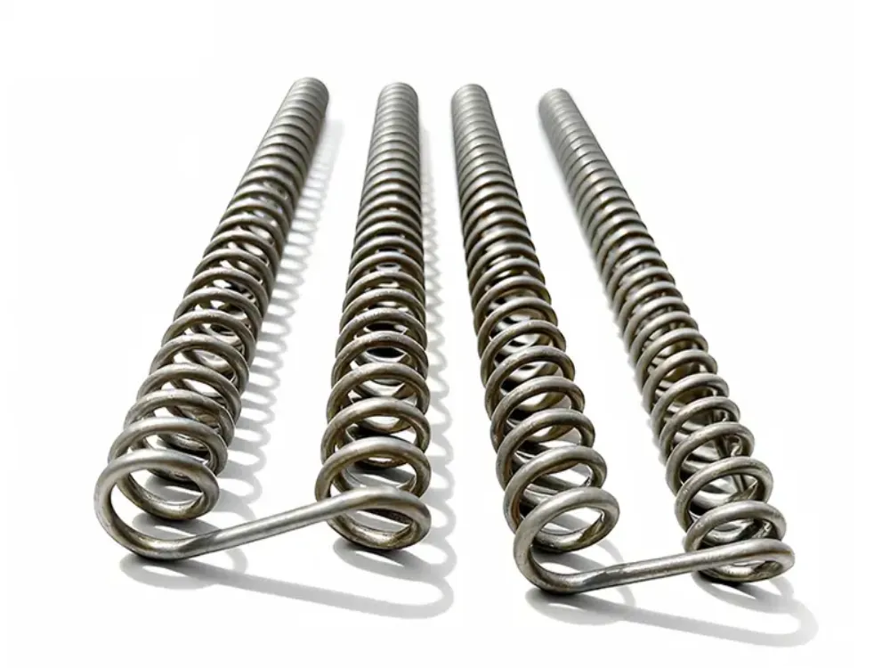
The furnace environment directly affects coil performance. Temperature, atmosphere, and heating cycles should therefore be considered during the design stage. A furnace heating coil also needs room and support for its intended thermal movement.
Record Gas and Support Conditions
Kanthal’s furnace-specific guidance explains the importance of atmosphere, contamination, and materials contacting the element. State the gas mixture, pressure, process residues, and support materials. A broad label such as “controlled atmosphere” is not enough.
Coils in grooves and coils on tubes do not exchange heat in the same way. Record installation direction, unsupported spans, support locations, and terminal transitions. Confirm the intended layout against the chosen material and cycle.
Retain the Useful Failure Checks
Heating coils can fail because of excessive temperature, poor support, unsuitable dimensions, or connection problems. The original failure checks remain useful as a short review list:
- Uneven turn spacing or local loading can contribute to hot regions.
- Surface degradation depends on the material and its environment.
- Poorly supported sections may deform during service.
- Loose connections or high contact resistance can create heat near a terminal.
The heating-element failure analysis guide covers diagnosis in more depth. Here, use those risks to identify the furnace heating coil inputs that need checking. A symptom alone does not prove a specific cause.
Review Forming and Cycling Together
As an element heats and cools, it expands and contracts. Coil pitch, supports, and installation method should match the operating cycle. Follow the approved furnace and element procedures rather than applying a generic stretching or heat-treatment recipe.
The official Kanthal workshop video below explains forming and material-family identification. It demonstrates an APM element, not a SPARK production process or a forming specification for every furnace heating coil.
Prepare the Drawing, RFQ, and Acceptance Record
Before ordering a furnace heating coil, check the dimensional and electrical requirements together. For replacement projects, an existing coil, drawing, or sample can provide a reference. Identify any service deformation so it is not mistaken for the original design.
Agree on What Will Be Supplied and Tested
| RFQ field | Information to agree |
|---|---|
| Material | Named grade, source data, and required supply condition |
| Drawing | Revision, units, dimension definitions, and measurement condition |
| Coil geometry | Wire size, OD/ID, pitch, axial length, heated length, and cold ends |
| Electrical requirement | Cold target, test temperature, measurement points, and hot-design basis |
| Assembly | Supports, terminals, connections, and installation space |
| Acceptance | Agreed dimensional/resistance limits, methods, and required documents |
| Purchase scope | Bare wire, formed coil, or specified assembly; quantity and delivery terms |
Do not assume a standard tolerance that the quotation never states. Ask how resistance will be measured and whether connections are included. Define the temperature and state of the part for dimensional inspection too.
For example, say whether the coil is free or held in place when its axial length is checked. Use the same reference points on the drawing and test record. Check that the furnace heating coil is in the agreed state before measuring it. Resolve any difference before comparing a result with a limit.
Illustrative Scenario: Different Quote Scopes
A buyer compares a bare-coil quote with one that includes terminal work and different inspection documents. The buyer aligns the supply form and acceptance requirements before comparing prices.
This scenario does not show a cost saving. It shows why a furnace heating coil quote needs an agreed technical scope. Unit price alone cannot establish that two offers meet the same order.
Keep Customization Within Confirmed Supply Scope
Gitane’s product overview lists custom processing and formed heating elements. Specific dimensions, tolerances, tests, and delivery scope still need confirmation for the proposed job. Do not treat a general capability statement as acceptance of every drawing.
To discuss a custom furnace heating coil, send GITANE the drawing and completed operating record. Include the unknowns as well as the targets so the quotation can address them.
Frequently Asked Questions and Next Steps
What Is a Furnace Heating Coil?
A furnace heating coil is a resistance element made from alloy wire or a specified formed material. Current generates heat within it. Its material and geometry must suit the furnace and electrical design.
Is Every Furnace Coil Made From Nichrome?
No. A nichrome heating coil uses a NiCr alloy, while FeCrAl is another common option. Select the actual grade against temperature, atmosphere, loading, and mechanical requirements.
Is There One Correct Pitch for Every Coil?
No universal pitch applies. Wire size, coil diameter, support, heat transfer, and the operating cycle all affect the design. State the pitch and its measurement condition on the drawing.
Does Matching Cold Resistance Approve a Replacement?
No. Review hot resistance, connections, dimensions, support, and service conditions as well. The cold test is one part of the furnace heating coil acceptance record.
What Should I Send for a Custom Order?
Provide the material record, drawing, electrical target, furnace conditions, cycle, quantity, and acceptance requirements. A sample or photograph can add context. Mark anything that still needs confirmation.
For a new or replacement furnace heating coil, contact GITANE with the element specification and furnace requirements. Keep the drawing, calculations, and acceptance record together so the proposed element can be reviewed as a complete design.